So far I’ve run through:
- Two RAMPs boards (maybe 3?) with attached Arduino processor boards
- One combined RAMPs based on a standardized MKS base design (MKS seems to be a working group of a number of Chinese firms). This worked well until it died.
- One Smoothie board from Kingprint based on an MKS sbase design
The smoothie board was received about ten days ago and in it’s short tenure did not manage to produce a single complete print. Not impressive. This is not an indictment of Smoothieware, but of the board quality.
I spend many (too many) hours trying to get it to behave before concluding that it was the board. In retrospect I shouldn’t have waited so long. This morning the onboard 5v regulator became flaky (I’m presuming since the activity lights were dark without the USB cable plugged in to supply offboard 5 volts) and in any case the board would lock up while printing whether printing via the USB connection or an onboard micro SD card.
The one good characteristic of the smoothieware hardware and software is the ability to be configured and to run the motors almost silently, so I’m going to try another sbase card but change the manufacturer – hopefully finding one with higher quality components.
JProbes
One special pain was trying to get the inductive probe I bought (and since replaced) to work. It turns out that 4mm is nowhere near enough clearance to reliably work with a probe between the bed surface, the end stop and later when the printer is actually printing and little problems happen.
The purpose of endstops are different in the Z axis when working with a probed bed surface than not. When one doesn’t use a probe, the endstop defines the bed surface, so you adjust the bed surface to correspond to the endpoint.
When a jprobe is in use the endstop indicates the maximum travel where the bed, which must be higher than the endstop indicates the surface. To do so the controller needs three things:
- The actual endstop position
- The measured jprobe surface
- The nozzle offset from the nozzle
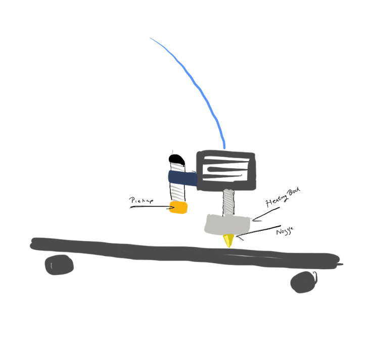
Can you figure it out? It isn’t easy, at least they didn’t make it easy. Is the pickup being above the nozzle +5mm or -5mm? Is it the position of the pickup they care about anyway since they system doesn’t sense that, it senses the actual detection which is 4mm (or 8mm with the new detector) below the pickup?
Gcode
The whole system is governed by a series of commands called gcodes. It makes sense except that more than half of them start with M.
Well, all the G###, like G0 or G92, have to do with motion, movement, or other actions. All the M### codes have to do with state or asking for state and they seem to mostly stick to the rules.
Although actual actions like X20 Y20 (move to 20,20 in the XY plane at the current Z) don’t need the G0 or G1 code if you don’t want to give it – way to be consistent! The machine will assume the current mode (absolute or relative motion) and interpret accordingly.
The gcodes are read by an interpreter that translates the codes into actual stepper commands that move things and turn the extruder on and off.
Then some gcodes work for some interpreters and not for others. This can lead to virtual duplicates between the interpreters.
The only thing going for it is that it is really pretty simple. It isn’t a programming language, it doesn’t require complex processing and virtually any person competent at software engineering could write in interpreter.